
The A3951SB and A3951SW are products designed for bidirectional pulse-width modulated current control of inductive loads. They are capable of continuous output currents to ±2A and operating voltages to 50V. Internal fixed off-time PWM current-control circuitry can be used to regulate the maximum load current to a desired value. The peak load current limit is set by the user’s selection of an input reference voltage and external sensing resistor.
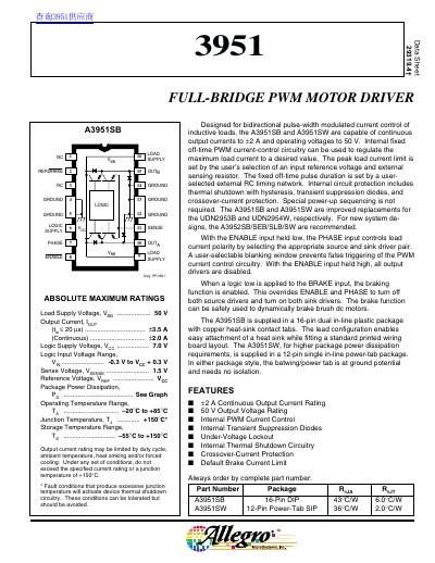
The document describes the A3951SB and A3951SW, which are full-bridge pulse-width modulated (PWM) motor drivers designed for bidirectional current control of inductive loads. These devices support continuous output currents up to 2A and operating voltages up to 50V.
| Continuous Output Current | +2 A |
|---|---|
| Output Voltage Rating | 50 V |
| Operating Temperature Range | -20°C to +85°C |
| Logic Supply Voltage Range | 4.5 V to 5.5 V |
The peak current limit defaults internally to a value approximated by Iap = 1-5 V/Rg.
No, special power-up sequencing is not required for these devices.