
The A3964SB and A3964SLB are designed for pulse-width modulated (PWM) current control of bipolar stepper motors, capable of continuous output currents to ±800 mA and operating voltages to 30 V. Internal fixed off-time PWM current-control circuitry can be used to regulate the maximum load current to a desired value. An internal precision voltage reference is provided to improve motor peak-current control accuracy. The peak load current limit is set by the user’s selection of an external resistor divider and current-sensing resistors. The fixed off-time pulse duration is set by user-selected external RC timing networks. The capacitor in the RC timing network also determines a user-selectable blanking window that prevents false triggering of the PWM current control circuitry during switching transitions. This eliminates the need for two external RC filter networks on the current-sensing comparator inputs. For each bridge, the PHASE input controls load current polarity by selecting the appropriate source and sink driver pair. For each bridge, the ENABLE input, when held high, disables the output drivers. Special power-up sequencing is not required. Internal circuit protection includes thermal shutdown with hysteresis, transient-suppression diodes, and crossover-current protection. The A3964SB is supplied in a 24-pin plastic DIP with copper heat sink tabs; A3964SLB is supplied
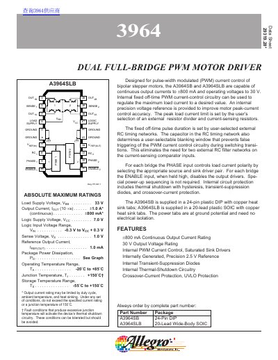
The document describes the A3964SB and A3964SLB, which are dual full-bridge PWM motor drivers capable of continuous output currents up to +800 mA and operating voltages up to 30 V. These devices are designed for pulse-width modulated (PWM) current control of bipolar stepper motors.
| Continuous Output Current | +800 mA |
|---|---|
| Output Voltage Rating | 30 V |
| Operating Temperature Range | -20°C to +85°C |
The device supports a continuous output current of up to 800 mA.
The driver can operate with a load supply voltage as high as 30 V.
The device operates within a temperature range of -20°C to +85°C.