
The A3966SA and A3966SLB are designed to drive both windings of a two-phase bipolar stepper motor. Each device includes two H-bridges capable of continuous output currents of ±650 mA and operating voltages to 30 V. Motor winding current can be controlled by the internal fixed-frequency, pulse-width modulated (PWM), current-control circuitry. The peak load current limit is set by the user’s selection of a reference voltage and current-sensing resistors. Except for package style and pinout, the two devices are identical. The fixed-frequency pulse duration is set by a user-selected external RC timing network. The capacitor in the RC timing network also determines a user-selectable blanking window that prevents false triggering of the PWM current-control circuitry during switching transitions. To reduce on-chip power dissipation, the H-bridge power outputs have been optimized for low saturation voltages. The sink drivers feature the Allegro patented Satlington output structure. The Satlington outputs combine the low voltage drop of a saturated transistor and the high peak current capability of a Darlington. For each bridge, a PHASE input controls load-current polarity by selecting the appropriate source and sink driver pair. For each bridge, an ENABLE input, when held high, disables the output drivers. Special power-up sequencing is not required. Internal circuit protection includes thermal shutdown with hysteresis.
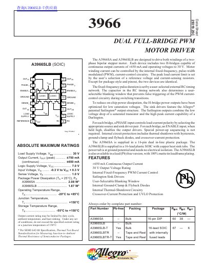
The Allegro MicroSystems A3966SA and A3966SLB are dual full-bridge PWM motor drivers designed to drive both windings of a two-phase bipolar stepper motor. Each device includes two H-bridges capable of continuous output currents of +650 mA and operating voltages up to 30 V.
| Continuous Output Current | +650 mA |
|---|---|
| Output Voltage Rating | 30 V |
| Logic Supply Voltage Range | 4.75 V to 5.5 V |
| Operating Temperature Range | -20°C to +85°C |
| Junction Temperature | +150°C |
The device supports a continuous output current of +650 mA.
Users must select a reference voltage and current-sensing resistors to set the limit.