
The document is the datasheet of UCC1580-1,-2,-3,-4 UCC2580-1,-2,-3,-4 UCC3580-1,-2,-3,-4 PWM controllers, introducing the features and characteristics of the product.
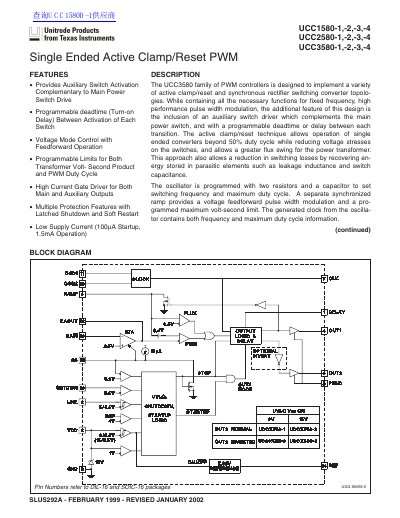
The document describes the UCC1580 family of Pulse Width Modulation (PWM) controllers designed for active clamp/reset and synchronous rectifier switching converter topologies. Key features include auxiliary switch activation complementary to the main power switch drive, programmable deadtime between transitions, voltage mode control with feedforward operation, and multiple protection features such as latched shutdown and soft restart.
| Supply Current (Startup) | 100 µA |
|---|---|
| Supply Current (Operation) | 1.5 mA |
| Oscillator Frequency | 370 kHz to 430 kHz |
| Reference Voltage (REF) | 5.0 V |
| Maximum Duty Cycle | 69 % |
The chip requires a low startup current of only 160 µA when VDD is under the UVLO threshold.
When the SHTDWN comparator input drops below its 0.5V threshold, OUT1 goes low and OUT2 continues to oscillate with guaranteed off time.