
The UCC3580 family of PWM controllers is designed to implement a variety of active clamp/reset and synchronous rectifier switching converter topologies. It includes an auxiliary switch driver that complements the main power switch and has a programmable deadtime or delay between each transition. The features of this product family include voltage mode control, programmable limits for transformer volt-second product and PWM duty cycle, high current gate driver, multiple protection features, and low supply current.
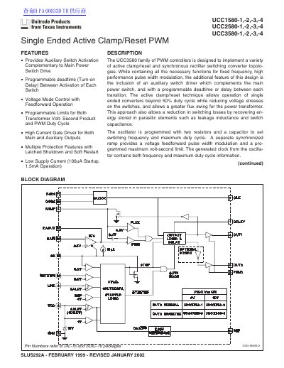
The UCC3580 family of PWM controllers is designed to implement active clamp/reset and synchronous rectifier switching converter topologies. The design includes an auxiliary switch driver that complements the main power switch with a programmable deadtime or delay between each transition. This approach allows operation of single-ended converters beyond 50% duty cycle while reducing voltage stresses on the switches and recovering energy stored in parasitic elements.
| Frequency | 370 to 430 kHz |
|---|---|
| Supply Current (Operating) | 1.5 mA |
| VDD On Threshold (-2/-4) | 15V |
| OUT1 Sourcing Current | 0.5A |
| OUT1 Sinking Current | 1A |
| OUT2 Drive Current | +0.3A |
| Temperature Range (UCC1580) | -55°C to +125°C |
| Temperature Range (UCC2580) | -40°C to +85°C |
| Temperature Range (UCC3580) | 0°C to +70°C |
A resistor from DELAY to GND programs the nonoverlap delay between OUT1 and OUT2.
The oscillator is programmed with two resistors and a capacitor to set switching frequency and maximum duty cycle.