
The TPS2046 and TPS2056 dual power-distribution switches are intended for applications where heavy capacitive loads and short circuits are likely. These devices incorporate in single packages two 135-mΩ N-channel MOSFET high-side power switches for power-distribution systems that require multiple power switches. Each switch is controlled by a logic enable compatible with 5-V and 3-V logic. Gate drive is provided by an internal charge pump that controls the power-switch rise times and fall times to minimize current surges during switching. The charge pump requires no external components and allows operation from supplies as low as 2.7 V. When the output load exceeds the maximum current limit, the internal short-circuit protection circuit will turn off the output and generate a logic high output, indicating an overcurrent condition. Thermal shutdown protection prevents permanent output switch damage due to excessive temperature. Undervoltage lockout function shuts off the output when the supply voltage drops below 2.7 V.
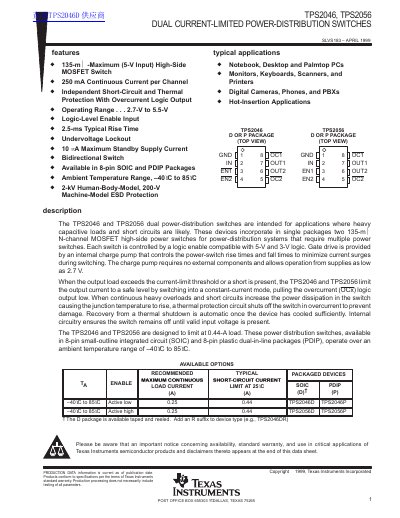
The TPS2046 and TPS2056 are dual power-distribution switches designed for applications involving heavy capacitive loads and short circuits. Each device incorporates two 135-mΩ N-channel MOSFET high-side power switches controlled by logic enable inputs compatible with 5-V and 3-V logic. These switches are intended for use in power-distribution systems for devices such as notebook PCs, monitors, and digital cameras.
The devices feature independent short-circuit and thermal protection. When an output load exceeds the current-limit threshold or a short circuit is present, the switches limit the output current to a safe level. A thermal protection circuit shuts off the switch if the junction temperature rises due to continuous heavy overloads, with automatic recovery once the device cools sufficiently. The switches operate from input voltages as low as 2.7 V and are available in 8-pin SOIC and PDIP packages.
| Continuous Current per Channel | 250 mA |
|---|---|
| Operating Voltage Range | 2.7 V to 5.5 V |
| Rise Time | 2.5 ms typical |
| Standby Supply Current | 10 µA maximum |
| ESD Protection (Human Body Model) | 2 kV |
| Operating Temperature Range | -40°C to 85°C |
The device can supply a minimum of 250 mA per switch.
The switches operate from supplies as low as 2.7 V up to 5.5 V.
A thermal protection circuit shuts off the switch when the junction temperature rises to approximately 140°C to prevent damage.