
This document is the installation guide for Smart pHTM water chemistry controller
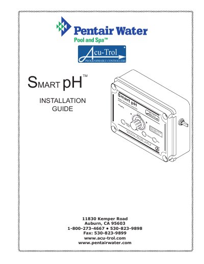
The Acu-Trol Smart pH 3 is a microprocessor-based automation system designed for continuous local monitoring and control of pH levels in pool and spa applications. It automatically adjusts water chemistry by increasing or decreasing pH using base or acid feeders, and can also manage CO2 gas systems.
This document details the installation process, including site preparation, mounting requirements, electrical connections (110 VAC), and plumbing setup for flow sensors and chemical feed pumps. It emphasizes safety precautions regarding grounding, power disconnection during servicing, and proper sensor placement to ensure accurate readings.
| Input Voltage | 125 V AC Maximum |
|---|---|
| Input Current | 5 AMPS (AC) |
| Operating Temperature | 30° - 110° F |
| Sensor Range | pH 4.22 - 9.78 |
The maximum input AC voltage must not exceed 125 V AC.
Yes, changing the jumper on the relay allows for different control voltages of 24V or a Dry Contact Switch.
They must be installed after the filter but before the chemical injector, with the flow sensor placed before the pH sensor.