
This is a synchronous reversible up-down counter with mode control. It is a 4-bit binary counter. Synchronous operation is achieved by clocking all flip-flops simultaneously, so that the outputs change simultaneously when instructed by the steering logic. This mode of operation eliminates the output counting spikes normally associated with asynchronous (ripple clock) counters. The outputs of the flip-flops are triggered on a low-to-high level transition of the clock input, if the enable input is low. A high enable input inhibits counting. Level changes at either the enable input or the down-up input should only be made when the clock input is high. The direction of the count is determined by the level of the down-up input. When low, the counter counts up, and when high, it counts down. This counter is fully programmable, meaning the outputs can be preset to any level by placing a low on the load input and entering the desired data at the data inputs. The output will change independent of the level of the clock input. This feature allows the counters to be used as modulo-N dividers by modifying the count length with the preset inputs. The clock, down-up, and load inputs are buffered to lower the drive requirement, which significantly reduces the drive requirement.
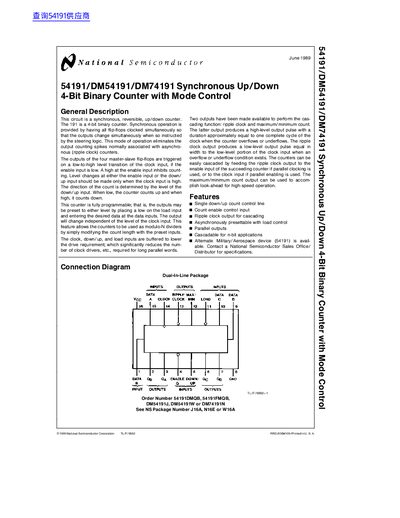
This document describes the 54191, a synchronous, reversible, up/down 4-bit binary counter. The circuit features simultaneous clocking of all flip-flops to eliminate output counting spikes associated with asynchronous counters. It includes a single down/up count control line and an enable input for controlling operation.
| Operating Temperature Range (Commercial) | -55°C to +125°C |
|---|
The direction of the count is determined by the level of the down/up input; when low, it counts up and when high, it counts down.
The outputs of the four master-slave flip-flops are triggered on a low-to-high level transition of the clock input if the enable input is low.