
Analog Devices ADuC841/ADuC842/ADuC843 Anomaly Sheet

This document describes the features and characteristics of MicroConverter® 12-Bit ADCs and DACs with Embedded High Speed 62-kB Flash MCU ADuC841/ADuC842/ADuC843.
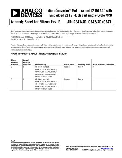

Analog Devices ADuC841/ADuC842/ADuC843 Anomaly Sheet - cover page
Brand
Analog Devices
Category
microcontrollers
Document type
Service Manual
Language
English
Pages
4
File format
PDF
File size
110 KB
Published
11 June, 2012
Updated
29 September, 2023
MD5 checksum
3808226B38A5EC89B41A05876BF3B643

About this manual

The document serves as an anomaly sheet for Silicon Revision E of the ADuC841/ADuC842/ADuC843 family. It details specific issues related to UART operation, stack pointer usage, I²C slave mode behavior, SPI interface configuration, and interrupt handling during flash operations.

What's inside

  • Mode 0 UART Operation
  • Use of the Extended Stack Pointer
  • I2C in Slave Mode with Stop Interrupt
  • I2C Data Transfer
  • SPI Interface Configuration
  • Interrupts During Reading/Writing to DATAFLASH/EE
  • PWM Operation
  • Watchdog Timer
  • Level Triggered Interrupt Operation
  • Stack Pointer in ULOAD Mode

Specifications

ADC Resolution12-Bit
Flash Memory Size62 kB
DATAFLASH/EE Capacity4 kB

Frequently asked questions

What is the workaround for UART Mode 0 operation?

UART Mode 0 is nonfunctional on these devices, and there are no workarounds provided.

How should code handle interrupts during DATAFLASH/EE read or write?

All interrupts must be disabled prior to a read or write operation by setting the EA bit to 0.

What is the workaround for the Watchdog Timer interrupt issue?

A double write to WDCON must be executed inside the ISR, with the first write resetting the timer.

Download PDF (110 KB)

More Analog Devices Manuals


View all Analog Devices manuals →