
The MAX1450 sensor signal conditioner is optimized for piezoresistive sensor calibration and temperature compensation. It includes an adjustable current source for sensor excitation and a 3-bit programmable-gain amplifier (PGA). The MAX1450 compensates offset, full-span output (FSO), offset tempco, FSO tempco, and FSO nonlinearity of silicon piezoresistive sensors via external trimmable resistors, potentiometers, or digital-to-analog converters (DACs), achieving a total typical error factor within 1% of the sensor’s inherent repeatability errors. The MAX1450 is capable of compensating sensors that display close error distributions with a single temperature point, making it ideal for low-cost, medium-accuracy applications. Although optimized for use with popular piezoresistive sensors, it may also be used with other resistive sensor types such as strain gauges. Maxim can customize the MAX1450 for unique requirements including improved power specifications. With a dedicated cell library consisting of more than 90 sensor-specific functional blocks, Maxim can quickly provide customized MAX1450 solutions. Contact the factory for additional information.
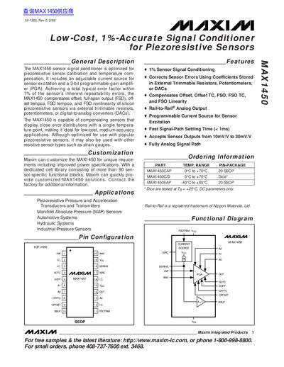
The MAX1450 is an integrated circuit designed to optimize signal conditioning for piezoresistive sensors. It includes an adjustable current source for sensor excitation and a 3-bit programmable-gain amplifier (PGA). The device compensates for offset, fullspan output (FSO), offset temperature coefficient (TC), FSO TC, and FSO nonlinearity using external trimmable resistors or digital-to-analog converters.
The document provides detailed electrical characteristics, pin descriptions, and functional diagrams. Key features include rail-to-rail analog output, fast signal-path settling time under 1ms, and the ability to accept sensor outputs ranging from 10mV/V to 30mV/V.
| Total Typical Error Factor | 1% of sensor's inherent repeatability errors |
|---|---|
| Supply Current (Ipp) | 2.8 to 3.5 mA |
| PGA Input Impedance | 1.0 MΩ |
| Common-Mode Rejection Ratio (CMRR) | 90 dB |
| PGA Gain Range | 39 to 221 V/V |
| Output Voltage Swing | (Vss + 0.25V) to (VDD - 0.25V) |
| Bridge Drive Current Range | 0.4 to 2.0 mA |
It is optimized for piezoresistive sensor calibration and temperature compensation, though it may also be used with other resistive sensor types such as strain gauges.
The fast signal-path settling time is less than 1ms.
The device is available in versions with operating temperatures from -40°C to +85°C and 0°C to +70°C.