
AN39-1 is an application note published by LT company in 1990, which introduces how to design the transformer to eliminate the adverse effects of parasitic capacitance in switching power supply.
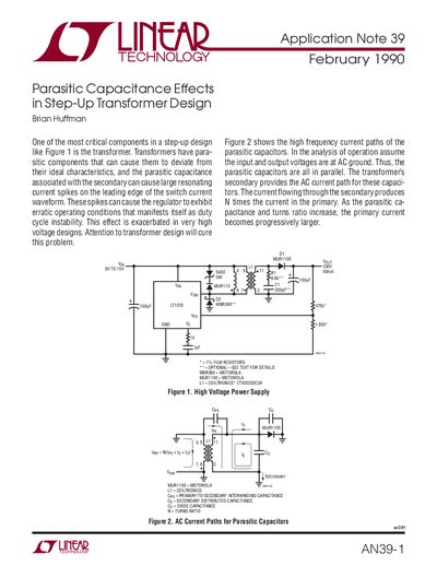
This document is an application note from Linear Technology Corporation addressing parasitic capacitance effects in high-voltage step-up transformer designs. It details how secondary parasitic capacitance creates resonating current spikes on the leading edge of switch waveforms, which can lead to erratic operating conditions and duty cycle instability in regulators like the LT1070.
The text analyzes these phenomena using circuit models and operating waveforms, explaining that the oscillatory response is formed by leakage inductance and reflected secondary capacitance. It identifies specific issues such as substrate diode conduction caused by high reverse current and provides mitigation strategies, including the use of Schottky diodes or RC snubbers on the secondary side to prevent unpredictable behavior.
Parasitic capacitance associated with the transformer secondary can cause large resonating current spikes on the leading edge of the switch current waveform, which manifests as duty cycle instability.
As the parasitic capacitance and turns ratio increase, the primary current becomes progressively larger due to the loading effects of secondary capacitors.
The internally fixed blanking time for the LT1070 is 400ns, which eliminates premature termination of the on pulse caused by leading edge current spikes.