
This document describes the features and characteristics of the ROHM DTC115E series digital transistors, including built-in bias resistors, inverter circuit configuration without external input resistors, elimination of parasitic effects with thin-film resistors, easy circuit design with only on/off conditions required for operation, and complementary PNP types.
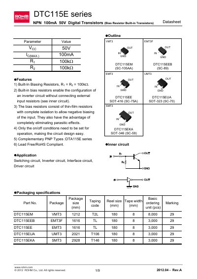
The DTC115E series digital transistors feature built‑in bias resistors (Ry = Re = 100 kΩ) that simplify inverter circuit design and eliminate external input resistors. The series includes NPN devices with a 50 V rating and complementary PNP types (DTA115E series).\n\nThe datasheet lists absolute maximum ratings, electrical characteristics, package dimensions, and packaging options for each variant (e.g., SOT‑416, SOT‑323, SOT‑346). It also contains a notice about usage restrictions and export compliance.
| Supply voltage (Voc) | 50 V |
|---|---|
| Input voltage (Vin) | -10 to +40 V |
| Output current (Io) | 20 mA |
| Collector current (I_Cmax) | 100 mA |
| Junction temperature (Tj) | 150 °C |
| Storage temperature range | -55 to +150 °C |
| Input resistance (Ry) | 70‑130 kΩ |
| Resistance ratio (R2/Ry) | 0.8‑1.2 |
| Built‑in bias resistor value | 100 kΩ |
The built‑in bias resistors are 100 kΩ (Ry = Re = 100 kΩ).
The maximum collector current is 100 mA.
The device is rated for a supply voltage of 50 V.