
The DHR-C5 is the transducer for the electronic measurement DC & distorted AC waveforms current, with galvanic isolation between the primary (High power) and the secondary (Low power) circuits.
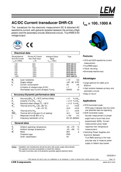
The DHR‑C5 is an AC/DC current transducer with galvanic isolation, delivering a true RMS 0‑5 V output for accurate power measurement. It is suitable for applications such as VFDs, SCRs, electronic ballasts and other controlled loads.
The manual details electrical data, isolation characteristics, mechanical dimensions, wiring connections and safety precautions, including supply voltage (+20‑50 VDC), isolation rating (1000 V), and mounting instructions for panel installation.
| Supply voltage | +20..50 VDC |
|---|---|
| Output voltage range | 0‑5 V (True RMS) |
| Isolation voltage rating | 1000 V |
| Mass | 260 g |
| Operating temperature range | -40..+70 °C |
| Storage temperature range | -40..+85 °C |
| Creepage distance | 11 mm |
| Clearance distance | 11 mm |
| Primary aperture | 32 mm |
| Panel mounting hole spacing | 4 holes @ 4.6 mm |
| Dimensions (L × W) | 25 mm × 70 mm |
It provides a true RMS voltage output of 0 to 5 V.
The transducer operates from a supply voltage of +20 to +50 VDC.
The device is rated for 1000 V isolation according to IEC 61010‑1 and CAT III standards.
Mount it using the four 4.6 mm holes; replace the M4 screws with appropriate length screws for the panel thickness.