
This document provides information about the availability of a certain product. Please contact the sales office for availability.
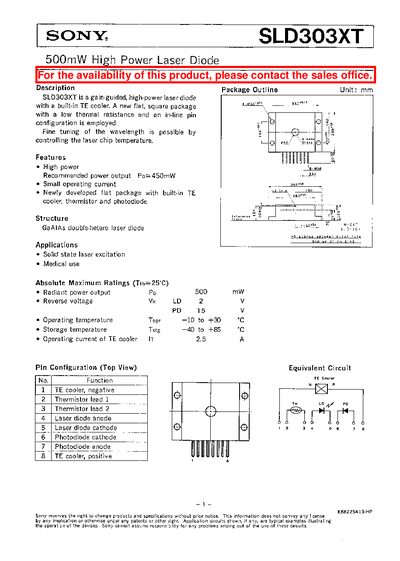
The Sony SLD303XT is a gain‑guided, high‑power laser diode with a built‑in TE cooler and a flat square package. It delivers up to 500 mW radiant power and is intended for solid‑state laser excitation and medical use.
The datasheet lists absolute maximum ratings, pin configuration, optical and electrical characteristics, wavelength dependence, and handling precautions such as mandatory eye‑protection goggles. Detailed graphs show radiant power versus current, slope efficiency, and temperature effects.
| Radiant power output | 500 mW |
|---|---|
| Threshold current (Ith) | 450 mA |
| Operating voltage (Vor) | 1.9‑3.0 V |
| Wavelength range | 770‑840 nm |
| Slope efficiency | 0.65‑0.9 mW/mA |
| Operating temperature | -10 °C to +30 °C |
| Storage temperature | -40 °C to +85 °C |
| TE cooler operating current | ≤ 2.5 A |
The recommended power output is 450 mW, with a maximum radiant power of 500 mW.
Eye protection is mandatory; always use safety goggles that block infrared rays and consider IR scopes or fluorescent plates for monitoring.
The device operates safely between –10 °C and +30 °C.
The top‑view pin configuration includes TE cooler negative (pin 1), thermistor leads (pins 2‑3), laser diode anode/cathode (pins 4‑5), photodiode cathode/anode (pins 6‑7), and TE cooler positive (pin 8).