
ICS601-01 is a low cost, low phase noise, high performance clock synthesizer for any applications that require low phase noise and low jitter. It is ICS's lowest phase noise multiplier, and also the lowest CMOS part in the industry.
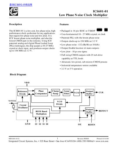
The ICS601-01 is a low‑cost, low phase‑noise clock multiplier IC designed for applications that require precise timing and minimal jitter. It uses a patented analog and digital PLL to multiply a 10‑27 MHz crystal or clock input up to 156 MHz output at 3.3 V or 5 V.
Key features include full‑swing CMOS outputs with 25 mA drive capability, an output‑enable function, and an industrial‑temperature version. The datasheet provides detailed pin assignments, electrical specifications, recommended external components, and package dimensions to aid designers in integrating the part into their circuits.
| Operating Voltage (VDD) | 3.0 V – 5.5 V |
|---|---|
| Input Frequency Range | 10 MHz – 27 MHz |
| Maximum Output Frequency | 156 MHz (3.3 V or 5 V) |
| Phase Noise (10 kHz offset) | -132 dBc/Hz |
| Maximum Jitter (one sigma, 125 MHz) | 18 ps |
| Output Drive Capability | 25 mA CMOS output |
The device accepts a 10‑27 MHz crystal or clock input.
It can generate output clocks up to 156 MHz at 3.3 V or 5 V.
Use 0.01 µF and 0.1 µF decoupling capacitors placed as close as possible to the supply pins.