
The MAX1614 is a high-side, N-channel power MOSFET driver with low-battery detection for battery power-switching functions in portable equipment. It features 3µA of quiescent current and 6µA of off-current and can be used in notebook computers, portable equipment, and hand-held instruments.
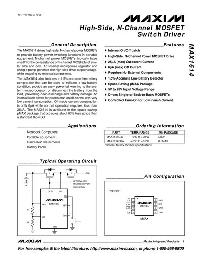
The MAX1614 provides high‑side switching for N‑channel power MOSFETs in portable equipment. It includes an internal micropower regulator, charge pump, and a low‑battery comparator that can signal an early power‑fail condition. The device operates from a 5 V to 26 V battery source and requires no external components for the charge‑pump circuitry.
Key features include a 1.5 % accurate low‑battery detector, an internal on/off latch for push‑button control, off‑mode current of only 6 µA, and the ability to drive single or back‑to‑back MOSFETs with controlled turn‑on to limit inrush current. The MAX1614 is supplied in an 8‑pin micro‑MAX package that saves board space.
| Input Voltage Range | 5 V to 26 V |
|---|---|
| Off‑mode Current Consumption | 6 µA |
| Maximum Off Current | 6 A (max) |
| Package Pin Count | 8 pins |
| Transistor Count | 264 |
The device operates from 5 V up to 26 V.
Off‑mode current consumption is only 6 µA.
The MAX1614 is supplied in an 8‑pin micro‑MAX package.