
The MAX1110/MAX1111 are low-power, 8-bit, 8-channel analog-to-digital converters (ADCs) that feature an internal track/hold, voltage reference, clock, and serial interface. They operate from a single +2.7V to +5.5V supply and consume only 85µA while sampling at rates up to 50ksps. The MAX1110’s 8 analog inputs and the MAX1111’s 4 analog inputs are software-configurable, allowing unipolar/bipolar and single-ended/differential operation. Successive-approximation conversions are performed using either the internal clock or an external serial-interface clock. The full-scale analog input range is determined by the 2.048V internal reference, or by an externally applied reference ranging from 1V to VDD. The 4-wire serial interface is compatible with the SPI™, QSPI™, and MICROWIRE™ serial-interface standards. A serial-strobe output provides the end-of-conversion signal for interrupt-driven processors. The MAX1110/MAX1111 have a software-programmable, 2µA automatic power-down mode to minimize power consumption. Using power-down, the supply current is reduced to 6µA at 1ksps, and only 52µA at 10ksps. Power-down can also be controlled using the SHDN input pin. Accessing the serial interface automatically powers up the device. The MAX1110 is available in 20-pin SSOP and DIP packages. The MAX1111 is available in small 16-pin QSOP and DIP packages.
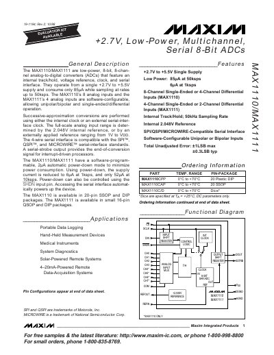
The MAX1110 and MAX1111 are low‑power, 8‑bit analog‑to‑digital converters that operate from a single +2.7 V to +5.5 V supply. They provide up to 8 analog inputs (MAX1110) or 4 inputs (MAX1111) and support unipolar, bipolar, single‑ended and differential modes.
The devices feature an internal 2.048 V reference, a 4‑wire serial interface compatible with SPI™, QSPI™ and MICROWIRE™, and an automatic 2 µA power‑down mode. Available in 20‑pin SSOP/DIP (MAX1110) and 16‑pin QSOP/DIP (MAX1111) packages, they are suited for portable data‑logging, medical instruments, and solar‑powered remote systems.
| Supply voltage range | +2.7 V to +5.5 V |
|---|---|
| Supply current at 50 ksps | 85 µA |
| Number of analog inputs | 8 (MAX1110) / 4 (MAX1111) |
| Internal reference voltage | 2.048 V |
| Serial interface compatibility | SPI, QSPI, MICROWIRE |
| Package types | 20‑pin SSOP/DIP (MAX1110), 16‑pin QSOP/DIP (MAX1111) |
They operate from a single +2.7 V to +5.5 V supply.
The ADCs consume only 85 µA while sampling at 50 ksps.
The MAX1110 provides eight analog inputs.
The 4‑wire serial interface is compatible with SPI™, QSPI™ and MICROWIRE™.