
Agilent HSMP-389x & HSMP-489x Series Surface Mount RF PIN Switch Diodes Data Sheet
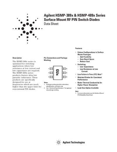
The HSMP‑389x series is optimized for switching applications that require low resistance at low current and low capacitance, while the HSMP‑489x series adds ultra‑low parasitic inductance for high‑frequency use beyond conventional PIN diodes. Both series are offered in various surface‑mount packages (SOT‑23/143, SOT‑323, SOT‑363) with unique configurations to save board space and improve thermal performance.
The datasheet provides electrical specifications such as forward current, peak inverse voltage, junction temperature limits, and typical series resistance and capacitance values. It also includes recommended PCB pad layouts, assembly guidelines, and ordering information for bulk or tape‑and‑reel options, along with contact details for technical support.
| Forward Current (I_F) | 1 A |
|---|---|
| Peak Inverse Voltage (PIV) | 100 V |
| Junction Temperature (Tj) Max | 150 °C |
| Storage Temperature Range | -65 °C to 150 °C |
| Maximum Soldering Temperature | 260 °C for 5 s |
The maximum soldering temperature is 260 °C for up to 5 seconds.
SOT‑23 package marking code is white, while SOT‑323 is laser marked; markings provide orientation, identification, and date code.
For low‑inductance series use, connect lead 1 and lead 2 together as shown in the internal connection diagram.