
The MAX7320 is an eight-channel, I2C port expander featuring eight push-pull outputs with selectable power-up logic states.
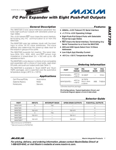
The MAX7320 is a 2‑wire serial‑interfaced PC port expander that provides eight push‑pull output ports with selectable power‑up logic states. It operates from a +1.71 V to +5.5 V supply and supports I2C communication up to 400 kHz. The device includes address inputs (ADO, AD2) that allow selection of one of 16 slave addresses and determine the default output states.
The datasheet includes absolute maximum ratings, electrical characteristics, timing diagrams, pin descriptions, and package information for QSOP and thin‑QFN options. It also compares the MAX7320 to other members of the MAX7319‑MAX7329 family and provides application notes for hot‑insertion and standby mode operation.
| Operating Supply Voltage (V+) | 1.71 V to 5.5 V |
|---|---|
| I2C Serial Clock Frequency | 400 kHz |
| Standby Current (typ) | 0.6 pA |
The MAX7320 supports an I2C serial clock frequency up to 400 kHz.
The device operates from a supply voltage of 1.71 V to 5.5 V.
The MAX7320 provides eight push‑pull output ports.
The slave address is selected using the ADO and AD2 address inputs, which also set the power‑up output logic states.