
This document introduces the features and characteristics of Vishay Dale M, C, and T type NTC thermistors.
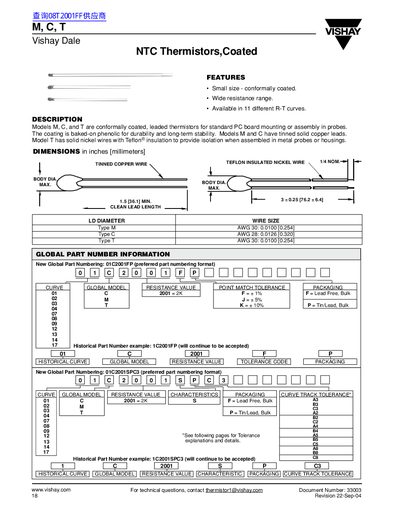
The Vishay M, C, and T NTC thermistors are conformally coated, leaded devices intended for standard PCB mounting or probe assembly. Models M and C feature tinned solid copper leads, while model T uses solid nickel wires with Teflon® insulation for isolation in metal housings.
The document provides detailed specifications such as body diameter, lead length, wire size, resistance values, tolerance schemes (point‑match and curve‑tracking), and temperature ranges. It also includes part‑numbering conventions, global part numbers, and a selection guide for choosing the appropriate curve and tolerance for a given application.
| Lead wire size (Model M) | AWG 30 (0.0100 in / 0.254 mm) |
|---|---|
| Lead wire size (Model C) | AWG 28 (0.0126 in / 0.320 mm) |
| Resistance tolerance (standard) | +5% or +10% |
| Temperature range (curve tracking) | 0 °C to +70 °C (also 20 °C to +50 °C, 0 °C to +100 °C, etc.) |
| Global part number format | 01C2001FP (preferred) |
Models M and C have tinned solid copper leads.
Standard leaded thermistors are calibrated to +5% or +10% tolerance, and tighter point‑match tolerances are also offered.
Curve‑tracking thermistors cover ranges such as 0 °C to +70 °C, 20 °C to +50 °C, 0 °C to +100 °C, and 25 °C to +90 °C.