
The MAX4063 is a differential-input microphone preamplifier optimized for high-performance, portable applications. The device features two selectable inputs, differential outputs, adjustable gain, an integrated low-noise bias source, and a low-power shutdown mode. Two input paths provide both differential and single-ended microphone sensing. The high-noise rejection of the differential input is ideally suited to an internal microphone where system noise and long-run PC board traces can degrade low-level signals. The single-ended input provides a simple connection to an external microphone. The differential and single-ended inputs have independent, adjustable gains that are set with a single external resistor. Differential outputs provide a full-scale signal of up to 6VP-P from a single 3V supply, optimizing the dynamic range of the amplified signal. A complete shut-down mode reduces the supply current to only 0.3µA and disables the microphone bias for the ultimate in power savings. The MAX4063 operates from 2.4V to 5.5V and is specified over the extended -40°C to +85°C operating temperature range. The MAX4063 is available in both 16-pin TQFN (4mm x 4mm x 0.8mm) and 14-pin TSSOP packages.
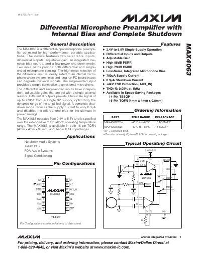
The MAX4063 differential‑input microphone preamplifier is optimized for high‑performance portable applications. It offers two selectable inputs (differential and single‑ended), adjustable gain set by a single resistor, an integrated low‑noise bias source, and a low‑power shutdown mode that reduces supply current to 0.3 µA.
The device operates from 2.4 V to 5.5 V, provides a full‑scale differential output up to 6 V p‑p, and features high power‑supply rejection (95 dB) and common‑mode rejection (79 dB). It is available in 14‑pin TSSOP and 16‑pin TQFN packages and is suited for internal or external microphone configurations in audio‑centric handheld devices.
| Supply Current (typical) | 0.75 mA to 1.1 mA |
|---|---|
| Operating Temperature Range | -40 °C to +85 °C |
| Differential Output Full‑Scale | up to 6 V p‑p |
| Input Resistance (each input) | 100 kΩ (typ) |
| THD+N (1 kHz) | 0.05 % |
| Power‑Supply Rejection Ratio (PSRR) | 95 dB |
| Common‑Mode Rejection Ratio (CMRR) | 79 dB |
An 11.11 kΩ resistor sets the differential gain to 20 V/V (about 26 dB).
Each input has a typical resistance of 100 kΩ.