
The MAX9981 dual high-linearity mixer integrates a local oscillator (LO) switch, LO buffer, LO splitter, and two active mixers. On-chip baluns allow for single-ended RF and LO inputs. The active mixers eliminate the need for an additional IF amplifier because the mixer provides a typical overall conversion gain of 2.1dB. The MAX9981 active mixers are optimized to meet the demanding requirements of GSM850, GSM900, and CDMA850 base-station receivers. These mixers provide exceptional linearity with an input IP3 of greater than +27dBm. The integrated LO driver allows for a wide range of LO drive levels from -5dBm to +5dBm. In addition, the built-in high-isolation switch enables rapid LO selection of less than 250ns, as needed for GSM transceiver designs. The MAX9981 is available in a 36-pin QFN package (6mm ✕ 6mm) with an exposed paddle, and is specified over the -40°C to +85°C extended temperature range.
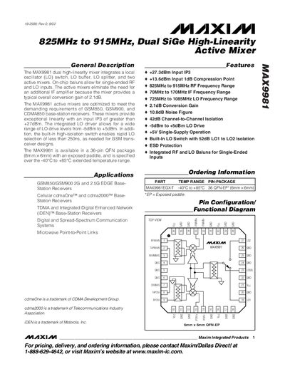
The MAX9981 dual high‑linearity mixer integrates a local‑oscillator switch, buffer, splitter, and two active mixers in a 36‑pin QFN package. On‑chip baluns allow single‑ended RF and LO inputs, and the mixer provides a typical overall conversion gain of 2.1 dB.
Designed for GSM850, GSM900, CDMA850, TDMA, iDEN and other 2G/2.5G base‑station receivers, the device offers high linearity (+27 dBm input IP3) and a fast LO‑selection time of less than 250 ns. It operates from –40 °C to +85 °C and requires a single 5 V supply.
| Input IP3 | >+27 dBm |
|---|---|
| Input 1 dB Compression Point | +13.6 dBm |
| RF Frequency Range | 825 MHz – 915 MHz |
| IF Frequency Range | 70 MHz – 170 MHz |
| LO Frequency Range | 725 MHz – 1085 MHz |
| Conversion Gain | 2.1 dB |
| Noise Figure | 10.8 dB |
| Channel‑to‑Channel Isolation | 42 dB |
| LO Drive Level | -5 dBm to +5 dBm |
| Supply Voltage | 5 V (single‑supply) |
| Supply Current | 260 mA – 325 mA |
| Input High Voltage (VIH) | 3.5 V |
| Input Low Voltage (VIL) | 0.4 V |
| LO Switch Isolation | 52 dB |
| Package | 36‑pin QFN (6 mm × 6 mm) with exposed paddle |
The MAX9981 provides a typical overall conversion gain of 2.1 dB.
The device has an input IP3 greater than +27 dBm.
The integrated LO driver accepts drive levels from –5 dBm to +5 dBm.
It is offered in a 36‑pin QFN package measuring 6 mm × 6 mm with an exposed paddle.