
The MAX12000 is a car and ship GPS front-end amplifier IC, which has two unconditionally stable low-noise amplifier stages, providing high gain and integrated I/O matching, minimizing the need for external matching components and eliminating the need for additional gain stages. The MAX12000 provides the option to place a bandpass ceramic or SAW filter between the two amplifier stages to provide a narrow-band output, further improving the noise performance of the GPS receiver. Additionally, a 3.4dB gain step is provided to compensate for variation in cable loss between different applications. MAX12000 is designed to operate at the GPS frequency of 1575MHz with a typical cascaded gain of 34.8dB and a 25mA supply current. The two LNA stages allow the use of a wide range of GPS filter types for maximum flexibility in system design. The final RF output pin, which drives the cable to the GPS receiver, is also the power-supply connection that accepts a DC supply in the +3.0V to +5.5V range. Alternatively, the DC supply can be applied to pin 4. The GPS front-end amplifier is designed on a low-noise, advanced SiGe process and is available in a lead-free, 10-pin TDFN surface-mount package (3mm x 3mm). Applications are integrated automobile and marine GPS receivers.
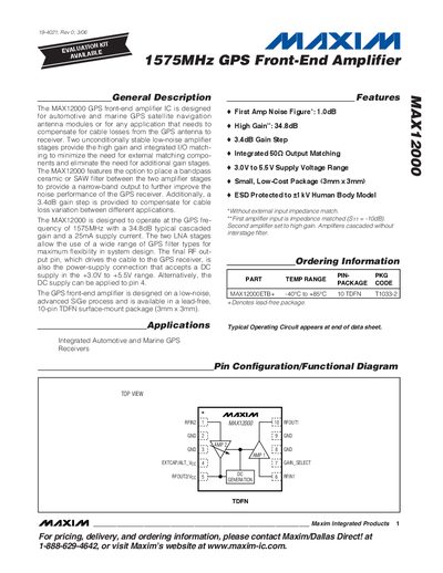
The MAX12000 is a 1575 MHz GPS front‑end amplifier designed for automotive and marine navigation antenna modules. It provides a typical cascaded gain of 34.8 dB with a low noise figure of 1.0 dB and includes a 3.4 dB gain‑step option for cable‑loss compensation.
The device operates from a 3.0 V to 5.5 V supply, draws about 25 mA, and is offered in a 3 mm × 3 mm 10‑pin TDFN package with exposed‑pad grounding and +1 kV HBM ESD protection. Detailed pin descriptions, absolute maximum ratings, and typical operating characteristics are provided.
| Noise Figure (typical) | 1.0 dB |
|---|---|
| Typical Gain | 34.8 dB |
| Supply Voltage Range | 3.0 V to 5.5 V |
| Supply Current (typical) | 25 mA |
| Package Size | 3 mm × 3 mm |
| ESD Protection | +1 kV HBM |
The device operates from 3.0 V to 5.5 V.
The typical noise figure is 1.0 dB.
It provides a typical gain of 34.8 dB, with an optional 3.4 dB gain step.
It is supplied in a 10‑pin TDFN package measuring 3 mm × 3 mm.