
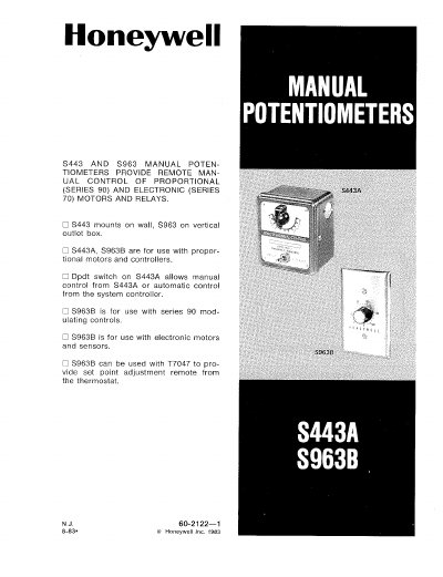
The manual describes Honeywell's S443A and S963B manual potentiometers, which provide remote manual or automatic control for proportional (Series 90) and electronic (Series 70) motors and relays. The S443A is a wall‑mount unit with a DPDT switch, while the S963B is designed for a vertical outlet box and supports multiple resistance ranges.
The guide covers mounting, wiring, and checkout procedures. It includes dimensions for mounting brackets, terminal connection details, typical wiring diagrams for 2‑wire and 3‑wire configurations, and instructions for setting the resistance scale and temperature markings. Installation must be performed by a trained service technician and comply with local electrical codes.
| Resistance range (S443A) | 0 to 135 Ω |
|---|---|
| Resistance range (S963B) | 0‑135, 240, 270, 360, 480, or 600 Ω |
| Finish | Gray (S443A), stainless steel (S963B) |
| Switch type (S443A) | DPDT switch |
Install a standard 2 × 4 in. outlet box that is at least 1‑3/4 in. deep.
Choose the appropriate resistance element (0‑135, 240, 270, 360, 480, or 600 Ω) as indicated for the model.
The knob is marked 40‑140 °F (5‑60 °C) or 60‑90 °F (16‑32 °C) depending on the selected range.