
AP8803 is a step-down DC/DC converter designed to drive LEDs with a constant current. The device can drive up to 7 LEDs, depending on the forward voltage of the LEDs, in series from a voltage source of 8V to 30V.
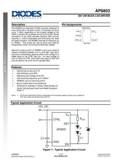
The AP8803 is a step‑down DC/DC converter designed to drive LEDs with a constant current. It can operate from 8 V to 30 V input and drive up to seven LEDs in series, providing up to 1 A of LED current. Features include high efficiency (up to 92 %), a switching frequency of up to 700 kHz, PWM/DG dimming control, and built‑in open‑circuit protection.
The datasheet details pin assignments, absolute maximum ratings, recommended operating conditions, and typical application circuits. It also covers component selection (inductor, capacitor, diode), thermal derating, and ordering information for the TSOT23‑5 package.
| Input voltage range | 8 V – 30 V |
|---|---|
| Maximum LED current | 1 A |
| Efficiency | up to 92 % |
| Switching frequency | up to 700 kHz |
| Package | TSOT23‑5 |
| Continuous switch current (Isw) | 1 A |
| Switching frequency (fosc) | 0.7 MHz |
The AP8803 can drive LED currents up to 1 A.
The output current is set by an external resistor connected between Vin and the SET pin.
It operates with an input voltage from 8 V up to 30 V.
Dimming is achieved by applying either a DC voltage or a PWM signal to the CTRL input pin.