
This document introduces the features of the 80c52x2 core, including the maximum core frequency, dual data pointer, full-duplex enhanced UART, three 16-bit timers/counters, 256 bytes of scratchpad RAM, 16/32KB on-chip flash EEPROM, 3KB flash EEPROM, 1KB EEPROM data, 1024 bytes of on-chip expanded RAM, and integrated power monitor (POR/PFD).
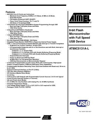
This manual describes the AT89C5131A-L 8‑bit Flash microcontroller, highlighting its 80C52X2 core, up to 48 MHz core frequency, dual data pointer, enhanced UART, three 16‑bit timers, and a full‑speed USB 1.1/2.0 module with multiple programmable endpoints. It also covers the on‑chip Flash (16/32 KB), EEPROM, expanded RAM, programmable LED outputs, watchdog timer, and power‑management features.
The document provides detailed pinout diagrams for PLCC‑52, VQFP‑64 and SO‑28 packages, signal tables for keypad, PCA, serial I/O, timers, LEDs, TWI, SPI, ports, and clock sources, as well as information on operating modes, power‑down and idle states, and hardware specifications such as supply voltage range and package options.
| Maximum core frequency | 48 MHz (X1 mode) / 24 MHz (X2 mode) |
|---|---|
| On‑chip Flash memory | 16 KB or 32 KB |
| Supply voltage range | 2.7 V to 3.6 V (3.0 V to 3.6 V required for USB) |
| USB compliance | USB 1.1 and 2.0 full‑speed compliant |
| Programmable LED outputs | 4 direct‑drive LED outputs |
The core can run at up to 48 MHz in X1 mode and 24 MHz in X2 mode.
It provides four direct‑drive LED outputs that can be programmed for different current levels.
The device operates from 2.7 V to 3.6 V, with 3.0 V to 3.6 V required for USB operation.
The microcontroller includes either 16 KB or 32 KB of on‑chip Flash memory.