
ADP5501 is a programmable current backlight driver with ambient light sensor input. It uses an efficient asynchronous boost converter to drive up to 6 white LEDs. The device has a 2.7 V to 5.5 V input voltage range, 128 programmable backlight LED current levels (maximum 30 mA), programmable backlight fade-in/fade-out times, programmable backlight dim and off times, ambient light sensing with autonomous backlight adjustment, 3 auxiliary LED current sinks, 64 programmable auxiliary LED current levels (maximum 14 mA), programmable auxiliary LED fade-in/fade-out times, programmable auxiliary LED on and off times (allows blinking), I2C-compatible serial interface, interrupt line for signaling an external processor (INT), hard reset (RST), current limit protection and thermal overload protection. The device is available in a small 4.0 mm × 4.0 mm, 24-lead LFCSP package.
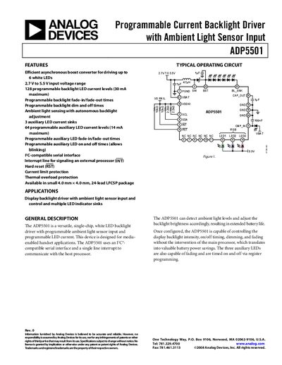
The ADP5501 from Analog Devices is a single‑chip boost converter designed to drive up to six white LEDs for display backlights. It features programmable LED current, three auxiliary LED sinks, and an integrated ambient light sensor that can automatically adjust brightness to extend battery life. Communication with a host processor is handled via an I²C‑compatible serial interface and an interrupt line.
The device operates over a 2.7 V to 5.5 V supply range and includes protection features such as over‑voltage, thermal shutdown, and current‑limit. Detailed specifications, pin functions, register maps, and typical performance curves are provided for designers of media‑enabled handheld and portable devices.
| Supply Voltage Range (VBAT) | 2.7 V to 5.5 V |
|---|---|
| I/O Voltage Range (VDDIO) | 1.8 V to 3.3 V |
| Shutdown Current (I_SD) | 0.1 µA to 1 µA |
| Backlight LED Driver Peak Current | 450 mA to 750 mA |
| Backlight LED Current Sink Full‑Scale | 26 mA to 32 mA |
| Ambient Light Sensor Full‑Scale Current | 0.7 mA to 1.2 mA |
| Thermal Shutdown Threshold | 150 °C |
| I²C Clock Frequency | 400 kHz |
It uses an I²C‑compatible serial interface with an interrupt line for status signaling.
The device provides three auxiliary LED current sinks that can be programmed independently.
The supply voltage (VBAT) operates from 2.7 V to 5.5 V, and the I/O pins accept 1.8 V to 3.3 V.