
The EL7585 is a multiple output regulator designed for use in large panel, TFT-LCD applications. It features a single boost converter with an integrated 3.5A FET, two positive LDOs for generating VON and VLOGIC, and a single negative LDO for generating VOFF. The boost converter can be programmed to operate in either P-mode or PI-mode to improve load regulation. The EL7585 also includes fault protection for all four channels. Once a fault is detected, the device is latched off until the input supply or EN is cycled. This device also incorporates an integrated start-up sequence for VBOOST, VOFF, then VON or for VOFF, VBOOST, and VON sequencing. The latter requires a single external transistor. The timing of the start-up sequence is set using an external capacitor. The EL7585 is specified for operation over the -40°C to +85°C temperature range.
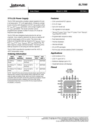
The EL7585 is a highly integrated power‑management IC designed for large panel TFT‑LCD applications. It combines a single boost converter, three linear regulators (two positive LDOs and one negative LDO), and built‑in fault protection for all four output channels. The device supports programmable start‑up sequencing and can operate in either P‑mode or PI‑mode for improved load regulation.
The datasheet provides absolute maximum ratings, thermal information, detailed electrical specifications, pin descriptions, typical performance curves, a block diagram, recommended external components, and a package outline drawing. It also includes application notes for LCD monitors, notebook displays, and industrial/medical LCD panels.
| Input voltage range | 3 V to 5 V |
|---|---|
| Boost output voltage range | 5.5 V to 20 V |
| Maximum switch current limit | 3.5 A |
| Output regulation accuracy | ±1 % |
| Operating temperature range | -40 °C to +85 °C |
| Package type | 20‑lead QFN |
The device operates with an input voltage between 3 V and 5 V.
The boost converter can deliver an output voltage from 5.5 V up to 20 V.
It is specified for operation from –40 °C to +85 °C.
The IC provides four regulated output channels and includes fault protection for all four.