
This document describes the features and characteristics of the ADRF6516 model, including dual programmable filters and variable gain amplifiers, continuous gain control range of 50 dB, digital gain control of 15 dB, a 6-pole Butterworth filter with a frequency range of 1 MHz to 31 MHz in 1 MHz steps and a corner frequency of 1 dB, preamplifier and postamplifier gain steps, IMD3 of >65 dBc for 1.5 V p-p composite output, HD2 and HD3 of >65 dBc for 1.5 V p-p output, differential input and output, flexible output and input common-mode ranges, optional dc offset compensation loop, SPI programmable filter corners and gain steps, power-down feature, and single 3.3 V supply operation. It is suitable for applications such as baseband IQ receivers, diversity receivers, ADC drivers, point-to-point and point-to-multipoint radio, and instrumentation medical.
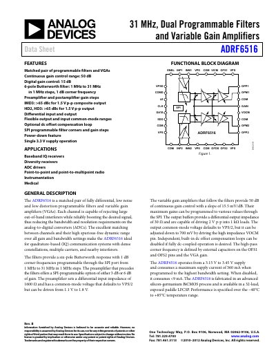
The ADRF6516 from Analog Devices combines two fully differential programmable filters with variable gain amplifiers (VGAs) in a single 32‑lead LFCSP package. It offers a six‑pole Butterworth response from 1 MHz to 31 MHz in 1 MHz steps, continuous gain control of 50 dB, and digital gain control of 15 dB, making it suitable for IQ receivers, diversity receivers, ADC drivers, and medical instrumentation.
The device operates from a single 3.15 V‑3.45 V supply, draws up to 360 mA at the highest bandwidth, and provides differential input impedance of 1600 Ω and output impedance of 30 Ω. SPI programming configures filter corners, gain steps, and offset‑compensation loops, while the part includes built‑in dc‑offset compensation and a power‑down feature.
| Frequency range | 1 MHz to 31 MHz |
|---|---|
| Continuous gain control range | 50 dB |
| Digital gain control range | 15 dB |
| Supply voltage | 3.15 V to 3.45 V |
| Differential input impedance | 1600 Ω |
| Differential output impedance | 30 Ω |
| Gain slope | 15.5 mV/dB |
| Group delay at 1 MHz | 135 ns |
The device operates from 3.15 V to 3.45 V.
It offers a continuous gain control range of 50 dB.
The filters cover 1 MHz to 31 MHz in 1 MHz steps.
The differential input impedance is 1600 Ω.