
The LT3572 is a highly integrated dual piezo motor driver capable of driving two piezo motors at up to 40V from a 5V supply. Each piezo driver can be independently turned on or off along with the boost converter. The boost regulator has a soft-start capability that limits the inrush current at start-up. The boost regulator switching frequency is set by an external resistor or the frequency can be synchronized by an external clock. A PGOOD pin indicates when the output of the boost converter is in regulation and the piezo drivers are allowed to start switching. The LT3572 is available in a (4mm × 4mm) 20-pin QFN package.
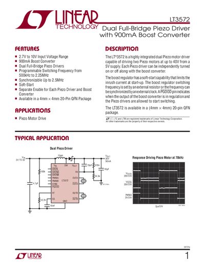
The LT3572 is a highly integrated dual piezo motor driver that can drive two piezo motors up to 40 V from a 5 V supply. It features a 900 mA boost converter, independent enable for each driver, and a soft‑start capability to limit inrush current.
The document details electrical characteristics, pin assignments, typical applications, and package information for the 20‑lead 4 mm × 4 mm QFN device, enabling designers to implement piezo motor drives with programmable switching frequencies up to 2.25 MHz.
| Input Voltage Range | 2.5 V to 27 V |
|---|---|
| Boost Converter Current | 900 mA |
| Switching Frequency Range | 500 kHz to 2.25 MHz |
| Operating Temperature Range | -40 °C to 85 °C |
| Package | 20‑Lead 4 mm × 4 mm Plastic QFN |
The device operates from 2.5 V up to 27 V.
The frequency is set by the resistor on the RT pin, giving a range of 500 kHz to 2.25 MHz, and can be synchronized via the SYNC pin.
PWMA and PWMB are the logic inputs for the drivers, while SHDN, SHDNA, and SHDNB control shutdown and enable the driver outputs.