
The LT3473/LT3473A are micropower step-up DC/DC converters with integrated Schottky diode and output disconnect circuitry. They are suitable for OLED bias and CCD bias conversion. The features include small size, low quiescent current, internal 1A, 36V switch, integrated Schottky diode, and PNP output disconnect, etc.
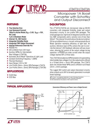
This handbook describes the LT3473 and LT3473A micropower 1 A boost converters with integrated Schottky diode and output‑disconnect circuitry. It lists key features such as low quiescent current, internal 1 A switch, and programmable reference override.
The document includes absolute maximum ratings, detailed electrical characteristics, pin descriptions, typical performance curves, and recommendations for inductors and capacitors. Package drawings for the 8‑lead and 12‑lead DFN versions are also provided.
| Minimum Operating Voltage | 2.2 V |
|---|---|
| Maximum Operating Voltage | 16 V |
| Switch Current Limit | 1.2 A |
| Switching Frequency | 0.9 – 14 MHz |
| Maximum Duty Cycle | 88 % – 92 % |
| Shutdown Voltage to Enable Chip | 14 V |
| PGOOD Current Capacity | 100 pA |
A 6.8 µH inductor is recommended for the LT3473.
The chip enables when the SHDN pin is driven to 14 V.
The converter operates between 0.9 MHz and 14 MHz.
The maximum duty cycle is between 88 % and 92 %.