
LTC1840 is a fan controller with two 8-bit current output DACs, two tachometer interfaces, and four general purpose I/O (GPIO) pins. It operates from a single supply with a range of 2.7V to 5.75V. A current output DAC is used to control an external switching regulator, which controls the fan speed. A current output DAC and tachometer allow a controller to form a closed control loop on fan velocity. The GPIO pins can be used as digital inputs or open drain pull-down outputs. The part features a simple 2-wire I2C and SMBus compat- ible serial interface that allows communication between many devices. The interface includes a fault status register that reflects the state of the part and which can be polled to find the cause of a fault condition. Other operational characteristics of the part, such as DAC output currents, GPIO modes, and tachometer frequency, are also pro- grammed through the serial interface. Two address pins provide nine possible device addresses. The BLAST pin is provided to force the DAC output currents to program the maximum regulator output voltages through a single pin and gate the operation of the serial access timer.
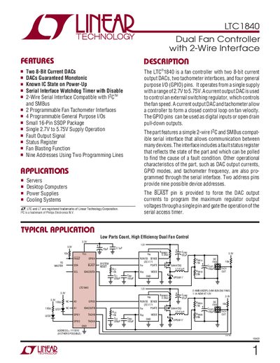
The LTC1840 is a fan controller that integrates two 8‑bit current DACs, two programmable fan tachometer interfaces, and four general‑purpose I/O pins. It operates from a single supply voltage of 2.7 V to 5.75 V and uses a simple 2‑wire serial (I²C/SMBus) interface for configuration and monitoring. The device includes a fault status register, address pins for nine possible I²C addresses, and a BLAST pin for immediate full‑scale DAC output.
The datasheet provides absolute maximum ratings, electrical characteristics, pin functions, timing diagrams, and typical performance curves. It also describes device addressing, register map, and a typical application circuit for controlling a pair of fans with automatic blast redundancy.
| Supply Voltage Range | 2.7 V to 5.75 V |
|---|---|
| DAC Resolution | 8 bits |
| Number of GPIO Pins | 4 |
| Package Type | 16‑lead SSOP |
| Maximum Number of I²C Addresses | 9 |
The LTC1840 operates from a single supply voltage between 2.7 V and 5.75 V.
The device provides two programmable fan tachometer interfaces.
Nine separate addresses can be set using the AO and A1 pins.
The BLAST pin forces the DAC output currents to full scale and can also trigger a timer‑based blast if the device is not accessed for about 1.5 minutes.