
The AD1990 is a 2-channel, bridge tied load (BTL), switching audio power amplifier with integrated Σ-Δ modulator. The modulator accepts a single-ended, analog input signal and converts it to a switching waveform to drive speakers directly. A digital, microprocessor-compatible interface provides control of reset, mute, and PGA gain, as well as feedback signals for thermal and overcurrent detection.
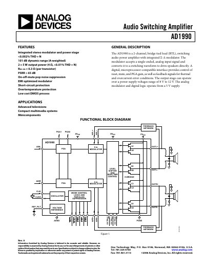
The AD1990 audio switching amplifier integrates a stereo Σ‑Δ modulator and a full‑bridge power stage capable of delivering 2 × 5 W into 4 Ω loads. It operates from 8 V to 12 V supply voltages and provides digital interfaces for mute, reset, gain control and error reporting.
The datasheet details specifications, pin configurations, typical performance curves, protection features such as thermal shutdown and over‑current protection, and example application circuits. It also includes mechanical dimensions and ordering information for the LFCSP package variants.
| Analog supply voltage (AVDD) | 5 V (typical) |
|---|---|
| Digital supply voltage (DVDD) | 5 V (typical) |
| Output power per channel | 2 × 5 W into 4 Ω |
| Total Harmonic Distortion + Noise (THD+N) | 0.003 % (typical) |
| Signal‑to‑Noise Ratio (SNR) | 102 dB (A‑weighted) |
| Dynamic Range | 102 dB (A‑weighted) |
| Input impedance | 20 kΩ |
| Output DC offset | ±4 mV |
Mute is an active‑low input; asserting MUTE pulls the output into a mute state with a delay of about 10 µs after the signal is asserted.