
This document describes the features and characteristics of SN54LS373, SN54LS374, SN54S373, SN54S374, SN74LS373, SN74LS374, SN74S373, and SN74S374 octal D-type transparent latches and edge-triggered flip-flops. These devices have 3-state outputs designed for driving highly capacitive or relatively low-impedance loads. The high-impedance 3-state and increased high-logic-level drive allow these registers to be connected directly to and drive the bus lines in a bus-organized system without the need for interface or pullup components. These devices are particularly suitable for implementing buffer registers, I/O ports, bidirectional bus drivers, and working registers.
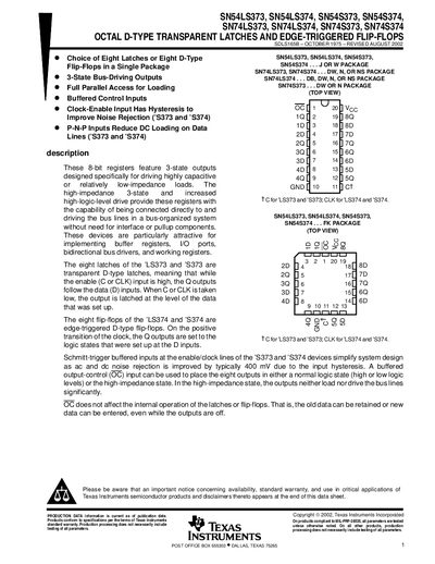
The document provides detailed information on the octal D‑type transparent latch family and edge‑triggered flip‑flop family, highlighting their 3‑state outputs, bus‑driving capability, and suitability for buffer registers, bidirectional bus drivers, and working registers. Electrical characteristics such as supply voltage, input thresholds, and output drive are listed, along with timing parameters and maximum clock frequency.
Additional sections cover ordering information, package drawings, mechanical dimensions, absolute maximum ratings, recommended operating conditions, and an important notice on product availability and warranty. The data sheet also includes functional tables, logic diagrams, and schematic representations of inputs and outputs.
| Operating temperature range | -55 °C to 125 °C |
|---|---|
| Maximum clock frequency | 50 MHz |
They are rated for a maximum clock frequency of up to 50 MHz.
The recommended operating temperature range is –55 °C to 125 °C.