
BTS 5215L is a high-side power switch chip launched by Infineon company, which uses Smart SIPMOS technology and has very low standby current, CMOS compatible input and fault diagnosis feedback. The chip is suitable for 12V and 24V grounded loads and can replace electromechanical relays, fuses and discrete circuits.
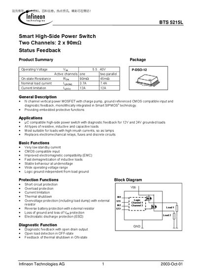
The BTS5215L is a smart high‑side power switch with two independent channels, each offering a 90 mΩ on‑state resistance and status‑feedback diagnostics. It is designed for 12 V and 24 V grounded loads and can replace electromechanical relays, fuses, and discrete circuits in resistive, inductive, or capacitive applications.
Key features include very low standby current, CMOS‑compatible inputs, integrated protection functions (short‑circuit, overload, thermal shutdown, over‑voltage, reverse‑battery, ESD), and open‑drain diagnostic outputs. The datasheet details pin assignments, electrical characteristics, thermal data, and recommended wiring for parallel operation.
| On‑state resistance (Ron) | 90 mΩ |
|---|---|
| Nominal load current (single channel) | 3.7 A |
| Nominal load current (parallel channels) | 7.4 A |
Each channel has an on‑state resistance of 90 mΩ.
A single channel can handle up to 3.7 A nominal load current.
ST1 and ST2 must be wired‑OR together with a single pull‑up resistor.