
The MAX5014/MAX5015 integrate all the building blocks necessary for implementing DC-DC fixed-frequency isolated power supplies. These devices are current-mode controllers with an integrated high-voltage startup circuit suitable for isolated telecom/industrial voltage range power supplies. Current-mode control with leading-edge blanking simplifies control-loop design and internal ramp compensation circuitry stabilizes the current loop when operating at duty cycles above 50% (MAX5014). The MAX5014 allows 85% operating duty cycle and could be used to implement flyback converters, whereas the MAX5015 limits the operating duty cycle to less than 50% and can be used in single-ended forward converters. A high-voltage startup circuit allows these devices to draw power directly from the 18V to 110V input supply during startup. The switching frequency is internally trimmed to 275kHz ±10%, thus reducing magnetics and filter component costs. The MAX5014/MAX5015 are available in 8-pin SO packages. An evaluation kit (MAX5015EVKIT) is also available.
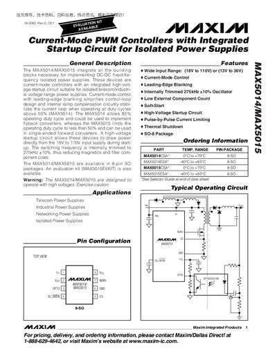
The MAX5014 and MAX5015 integrate the building blocks needed for fixed‑frequency isolated DC‑DC power supplies. They operate in current‑mode with a high‑voltage startup circuit, supporting input voltages from 18 V to 110 V (or 13 V to 36 V) and an internally trimmed 275 kHz oscillator. The MAX5014 can run up to an 85 % duty cycle for flyback converters, while the MAX5015 is limited to 50 % duty cycle for single‑ended forward converters.
Both devices are offered in an 8‑pin SO package and are supported by an evaluation kit (MAX5015EVKIT). The datasheet provides absolute maximum ratings, electrical characteristics, thermal shutdown parameters, pin descriptions, and typical application circuits for telecom and industrial power supplies.
| Input Voltage Range | 18 V to 110 V (or 13 V to 36 V) |
|---|---|
| Switching Frequency | 275 kHz ±10 % |
| Package Type | 8‑pin SO (SO‑8) |
| Thermal Shutdown Temperature | 150 °C |
The devices accept a wide input range of 18 V to 110 V, or 13 V to 36 V depending on the configuration.
Both controllers use an internally trimmed oscillator set to 275 kHz with a ±10 % tolerance.
They are supplied in an 8‑pin SO (SO‑8) package.