
This data sheet describes the features and functions of the Intersil X9119 single supply/low power/1024 tap/2-wire bus single digitally controlled (XDCP™) potentiometer. The potentiometer is implemented using 1023 resistive elements in a series array and has a 10-bit resolution. Between each element are tap points connected to the wiper terminal through switches. The user can control the position of the wiper on the array through the 2-wire bus interface. The potentiometer also has an associated volatile Wiper Counter Register (WCR) and a four non-volatile Data Registers that can be directly written to and read by the user. The contents of the WCR control the position of the wiper on the resistor array through the switches. Powerup recalls the contents of the default data register (DR0) to the WCR. The XDCP™ can be used as a three-terminal potentiometer or as a two terminal variable resistor in a wide variety of applications including control, parameter adjustments, and signal processing.
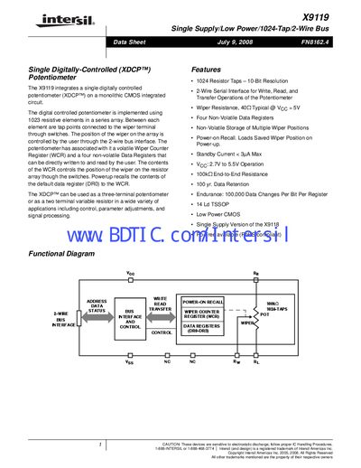
The X9119 integrates a 1024‑tap digitally controlled potentiometer (XDCP™) on a monolithic CMOS IC. It offers a 2‑wire serial bus for read, write and transfer operations, volatile wiper counter register and four non‑volatile data registers.
Typical applications include gain control, voltage reference, audio volume, sensor conditioning and programmable resistors. The device is supplied in a 14‑lead thin‑shrink small‑outline plastic (TSSOP) package and operates from 2.7 V to 5.5 V with standby current below 3 µA.
| Resolution | 1024 resistor taps (10‑bit) |
|---|---|
| Supply Voltage | 2.7 V to 5.5 V |
| Standby Current | < 3 µA max |
| Data Retention | 100 years |
| Endurance | 100,000 data changes per bit per register |
| Non‑volatile Data Registers | Four |
| Package | 14‑lead TSSOP |
It uses a 2‑wire serial bus (SDA/SCL) for read, write and transfer operations.
The X9119 provides four non‑volatile data registers.
The standby current is less than 3 µA.
The device operates from 2.7 V to 5.5 V.