
The AD8208 is a single-supply difference amplifier ideal for amplifying and low-voltage differential voltage signals. It features high voltage, high precision, and wide operating temperature range.
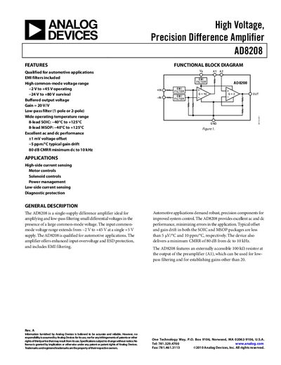
The AD8208 is a single‑supply difference amplifier designed to amplify small differential voltages while tolerating large common‑mode voltages. It offers a fixed system gain of 20 V/V, EMI filtering, and an external 100 kΩ resistor for gain adjustment and low‑pass filtering.
Typical applications include high‑side and low‑side current sensing, motor control, solenoid control, and power‑management circuits. The device is qualified for automotive use, operates from a 4.5 V–5.5 V supply, and maintains performance over a temperature range of –40 °C to +125 °C.
| System Gain | 20 V/V |
|---|---|
| Input Common‑Mode Voltage Range | −2 V to +45 V |
| Supply Voltage (Operating Range) | 4.5 V to 5.5 V |
| Quiescent Current (Typical) | 1.6 mA |
| CMRR (Minimum) | 80 dB |
| Absolute Maximum Supply Voltage | 12 V (continuous), −24 V to +80 V (survival) |
| Operating Temperature Range | −40 °C to +125 °C |
The AD8208 provides a fixed system gain of 20 V/V.
It accepts a common‑mode voltage from –2 V to +45 V when powered from a 5 V supply.
A low‑pass filter can be implemented by connecting the output of A1 to A2 and adding a capacitor to ground, using the internal 100 kΩ resistor.