
AD5204/AD5206 are 4-/6-channel digital potentiometers with 256 positions, which can replace mechanical potentiometers. Each channel has a fixed resistance value and can be programmed through the SPI interface. Suitable for mechanical potentiometer replacement, instrumentation calibration, programmable voltage-to-current conversion, and other applications.
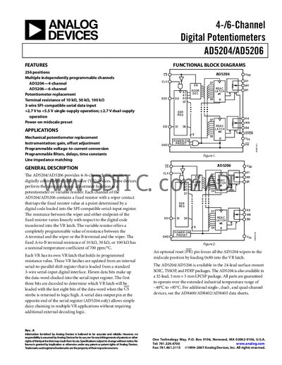
The AD5204 (4‑channel) and AD5206 (6‑channel) are digitally programmable potentiometers that replace mechanical potentiometers in instrumentation, voltage‑to‑current conversion, programmable filters, and line‑impedance matching. Each channel provides a fixed resistor with a wiper that can be set via an 11‑bit SPI‑compatible serial interface, offering 256 discrete positions.
The devices are offered in 24‑lead SOIC, TSSOP, PDIP packages and, for the AD5204, a 32‑lead LFCSP package. They operate over an industrial temperature range of –40 °C to +85 °C with a single‑supply voltage of +2.7 V to +5.5 V (or dual‑supply). Pin functions include Chip Select (CS), Midscale Preset (PR), and serial data I/O, enabling daisy‑chaining and flexible system integration.
| Number of channels | 4 (AD5204) / 6 (AD5206) |
|---|---|
| Resolution | 8 bits |
| Terminal resistance options | 10 kΩ, 50 kΩ, 100 kΩ |
| Operating temperature range | -40 °C to +85 °C |
| Supply voltage range (single‑supply) | +2.7 V to +5.5 V |
| Power dissipation | 0.3 mW |
CS is the Chip Select input (active low); when CS returns high, the data in the serial input register is decoded and loaded into the target RDAC latch.
The PR (Preset) pin, which is active low, forces all RDAC latches to the midscale position by loading 0x80 into each latch.
The devices are guaranteed to operate up to +85 °C (with a minimum of –40 °C).