
This document describes the construction and operation of the 41-100K 2 CO (HI-LO) overcurrent relay, which includes an overcurrent unit, an indicating switch or an AC auxiliary switch, and an indicating instantaneous trip unit when required. The different relays use different electromagnet designs to generate out-of-phase air gap fluxes for contact closing torque. The operation principle of the DC indicating contactor switch unit is also explained.
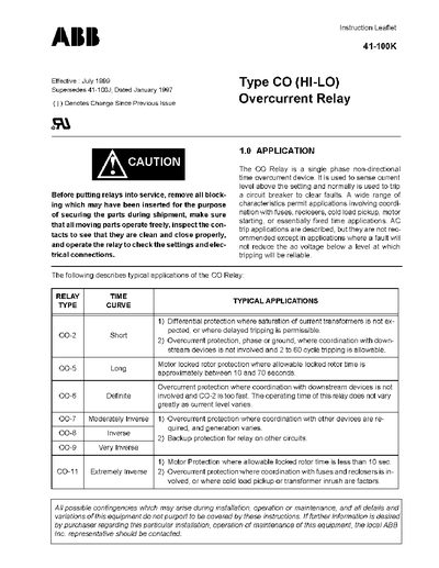
The CO (HI-LO) Overcurrent Relay is a single‑phase, non‑directional time overcurrent device used to sense currents above a set level and to trip a circuit breaker. Typical applications include differential protection, motor locked‑rotor protection, and coordination with fuses, reclosers, or load‑pickup conditions.
The leaflet details the relay’s construction (electromagnet, indicating contactor switch, AC auxiliary switch, and instantaneous trip unit), provides wiring and characteristic curves, and gives step‑by‑step instructions for installation, tap and time‑dial settings, adjustments, performance checks, routine maintenance, and calibration. Parts lists and renewal part ordering information are also included.
| Current range (high) | 1 – 12 A |
|---|---|
| Main contact rating | 30 A at 250 V |
Connect the lead located in front of the tap block to the desired setting using a screw connection.
Mount the relay vertically with the mounting stud or use the four mounting holes on the flange for semiflush mounting; grounding can be done via the stud or mounting screws.
Set the time dial to position 6 with the lowest tap, apply tap‑value current ± 3 %; the contacts should move at those currents.