
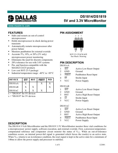
The Maxim DS1814 (5‑V) and DS1819 (3.3‑V) MicroMonitor ICs monitor power‑supply, software execution, and external override conditions for microprocessors. They provide reset control, push‑button reset, and watchdog timer functions in a low‑cost SOT‑23‑5 package.
The document details pin assignments, operating characteristics, absolute maximum ratings, recommended operating conditions, timing diagrams, and part‑marking codes for the A, B, and C device variants.
| Supply Voltage (VCC) Typical | 5.5 V |
|---|---|
| Reset Active Time | 140 ms (minimum) |
| Watchdog Timeout (typical) | 1.12 s |
| Input Capacitance | 5 pF |
| Output Capacitance | 7 pF |
The push‑button reset generates a reset signal of at least 140 ms minimum.
The watchdog timer can be disabled by leaving the ST input floating (tri‑stated).
The VCC pin may be exposed to voltages from –0.5 V to +7.0 V relative to ground.
Pin 3 (PBRST) on DS1814 A and C, and pin 3 (RST) on DS1814 B provide the push‑button reset input.