
GW9149 is a dedicated circuit designed for infrared remote control receiving systems. It can complete 10 control functions and has features such as parallel output, hold pulse, and cycle pulse.
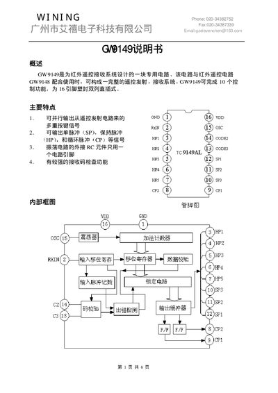
The GW9149 is a dedicated circuit designed for infrared remote‑control receiver systems. When paired with the GW9148 transmitter it forms a complete remote‑control solution offering up to ten control functions in a 16‑pin DIP package.
The document provides an overview of the main features, internal block diagram, electrical parameters, pin assignments, functional descriptions, encoding order, and package dimensions, helping designers integrate the device into their applications. This manual is written in Chinese.
| Working voltage (Vdd) | 6.0 V |
|---|---|
| Input/Output voltage range | Vss‑0.3~Vdd+0.3 V |
| Dynamic power consumption | 200 mW |
| Operating temperature | -20~+75 °C |
| Storage temperature | -55~+125 °C |
| Oscillation frequency | 38 kHz |
| Supply voltage (typical) | 5 V |
| Supply current (no load) | 1.6 mA |
| Pull‑up resistor (Rup) | 245 kΩ |
The GW9149 operates at a working voltage of 6.0 V.
The GW9149 is provided in a 16‑pin DIP package.
The internal RC oscillator runs at 38 kHz.
Pin 1 is GND (ground) and pin 2 is RxIN, the receive‑signal input.