
The XC9505 series are PWM controlled, PWM/PFM switching 2 channel (step-down and inverting) DC/DC controller ICs.
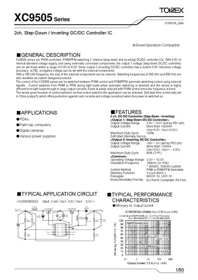
The XC9505 series from Torex are dual‑channel DC‑DC controller ICs that provide a step‑down (buck) output and an inverting output in a single package. They operate from 2.0 V to 10.0 V supply voltage and support PWM, PFM, or hybrid control modes selectable via external pins.
The datasheet details electrical characteristics, pin assignments, typical application circuits, and marking information for the MSOP‑10 and USP‑10 packages. It also includes design equations for setting output voltages and notes on soft‑start, standby current, and RoHS compliance.
| Operating Voltage Range | 2.0 V ~ 10.0 V |
|---|---|
| Oscillation Frequency | 180 kHz (custom 300 kHz, 500 kHz) |
| Maximum Duty Cycle (Output 1) | 100 % |
| Output Voltage Range (Step‑Down) | 0.9 V ~ 6.0 V |
| Output Voltage Range (Inverting) | -30 V ~ 0 V |
Soft‑start time is internally set to 10 ms for output 1.
The IC is available in MSOP‑10 and USP‑10 packages.
Stand‑by current is between 1.0 A and 3.0 A.