
This document introduces the installation precautions for the paper tray selection items D13/D14 of the Sharp digital copiers AR-M350/AR-M450, which were released in February 2003. During the installation of D13/D14, the installation personnel need to perform the Sim simulation code self-test operation, including executing Sim40-12 operation and selecting different projects to adjust the position of the paper tray size baffle. In addition, it is mentioned that when D14 cannot detect the paper tray size correctly, it is necessary to confirm whether the first paper tray is installed in reverse with the second and third paper trays, and pay attention to the position of the paper tray size block when exchanging the upper and lower paper trays.
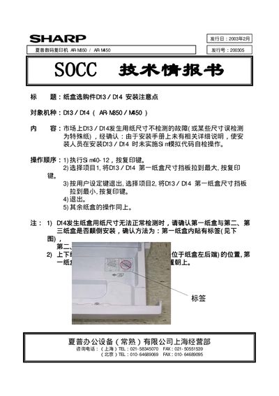
This guide provides step‑by‑step installation instructions for the DI3 and DI4 modules of the Sharp AR‑M350/AR‑M450 digital copiers. It outlines the required adjustments, the order of operations, and special notes to avoid common faults during setup.
The document also includes important safety notes, such as checking the size settings for DI4 and ensuring proper alignment before finalizing the installation. Contact information for Sharp support in Shanghai and Beijing is provided at the end of the guide. This manual is written in Japanese.
1) Set S n40‑12 and start the printer. 2) Move item 1, set DI3/DI4 first size indicator to maximum and confirm. 3) Pull the lever, move item 2, set DI3/DI4 first size indicator to minimum and confirm. 4) Exit. 5) Repeat for remaining items.
When measuring DI4 size, ensure the first and second (or third) size indicators are correctly aligned; the guide notes special handling if the size measurement is abnormal.