
This Application Note describes how to use the multi-purpose output ports of Philips Industrial UARTs to implement an automatic “switching” structure for RS-485 protocol (sometimes called 9-bit or multipoint mode) applications when using transmitter control. An interrupt is generated when the inversion takes place.
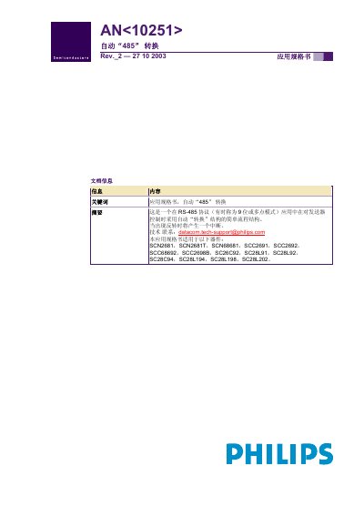
The AN10251 application specification describes an automatic RS‑485 conversion structure for Philips industrial UARTs. It explains how the OP pin is controlled by the transmitter to switch between transmit and receive modes without software monitoring, and provides programming guidance for enabling this feature.
The document lists the compatible UART devices, details the polarity of the OP pin during transmission and reception, and outlines the interrupt generation mechanism when the signal polarity reverses. Legal disclaimer, licensing and patent information are also included. This manual is written in Chinese.
| OP pin polarity | Logic low (Vss) during transmission, logic high (Vcc) during reception |
|---|---|
| Interrupt trigger | Interrupt is generated when the signal polarity reverses |
During transmission the OP pin is driven low (Vss); during reception it is driven high (Vcc).
An interrupt occurs when the signal polarity reverses, which the OP pin state‑change detector detects.