
This manual provides detailed information on AME 55 QM and AB-QM, including technical specifications, installation instructions, maintenance instructions, etc.
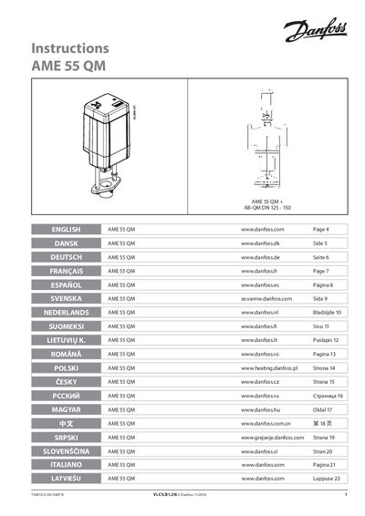
This manual contains safety notes and installation guidance for the AME 55 QM actuator. It stresses that assembly, start‑up and maintenance must be performed by qualified personnel and that the system must be depressurised before work begins.
The document describes wiring connections for the control (Y, SN) and output (X) signals, the required 24 V AC supply, and detailed DIP switch settings that define voltage or current control ranges, direction, sequencing and flow characteristics. A function‑test section explains LED indications for normal operation, self‑adjustment and fault conditions.
| Supply voltage | 24 V~ -15% to +10%, 50 Hz |
|---|---|
| Control signal (voltage) | 0 V … 10 V |
| DIP switches default position | All OFF |
| Power signal for 3‑point mode | 24 VAC |
It requires a 24 V AC supply with a tolerance of –15 % to +10 % at 50 Hz.
Change the position of the RESET switch (switch No. 9); the LED will flash while the self‑adjustment routine runs.