
This datasheet details a dual‑channel brushed DC motor driver with 12 A per channel, 6.5‑29 V input, protection circuits, pinout, and performance…
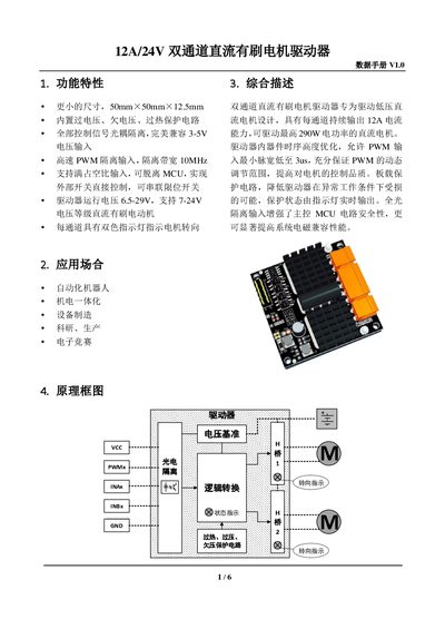
The driver is designed for low‑voltage brushed DC motors, offering two independent channels each capable of delivering up to 12 A continuous current (up to 290 W). It features built‑in over‑voltage, under‑voltage and over‑temperature protection, fully opto‑isolated control signals, and a high‑speed PWM input with 10 MHz bandwidth.
Technical data include operating voltage range, current limits, PWM characteristics, logic input levels, and mechanical dimensions. Typical applications cover automation robots, mechatronics, equipment manufacturing, research, and electronic competitions. Safety notes advise proper power wiring, fuse protection, and handling precautions. This manual is written in Chinese.
| Power supply voltage (VP) | 6.5‑29 V |
|---|---|
| Over‑voltage protection | 29.3 V |
| Under‑voltage protection | 6.3 V |
| Continuous output current per channel | 12 A |
| Peak output current (100 ms) | 70 A |
| Peak output current (10 µs) | 200 A |
| Logic input voltage | 3‑5.5 V |
| Logic input current (VCC=5 V) | 15 mA |
| PWM input frequency | 18‑60 kHz |
| Minimum PWM pulse width | 3 µs |
| Operating temperature | -25 °C to 85 °C |
| Dimensions (L×W×H) | 50 mm × 50 mm × 12.5 mm |
Each channel can continuously output 12 A.
The driver includes over‑voltage, under‑voltage, and over‑temperature protection circuits.
A PWM frequency between 18 kHz and 60 kHz is recommended; frequencies below 10 kHz may cause audible noise.
The board measures 50 mm × 50 mm with a height of 12.5 mm (15 mm including the power terminal height).