
This guide provides specifications, installation steps, wiring details, and performance data for the Mitsubishi Electric FX 1N-232-BD RS‑232C Communication…
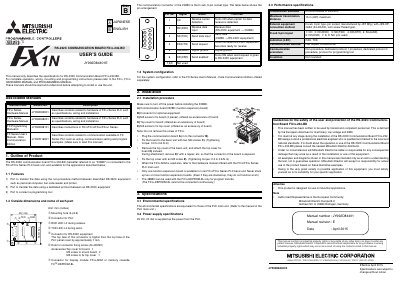
The RS‑232C Communication Board FX 1N-232-BD expands the FX1S/FX1N series PLCs with a 9‑pin D‑sub RS‑232C port for connecting PCs, barcode readers, printers, or a programming tool. It is intended for industrial applications and must be used together with the FX series hardware and programming manuals.
Installation requires the power to be switched off, the board to be fixed to the PLC with two M3 screws, and the top cover to be replaced (torque 0.3‑0.6 N·m). The board draws 5 V DC at 20 mA from the PLC, supports half‑duplex bi‑directional communication, and can transmit up to 15 m. LEDs indicate receive (RXD) and transmit (TXD) activity.
| Power supply | 5 V DC, 20 mA (supplied from PLC) |
|---|---|
| Maximum transmission distance | 15 m (49 ft) |
| Communication method | Half duplex, bi‑directional |
| RS‑232C connector type | D‑sub 9‑pin socket |
| LED indicators | RXD LED lit during receive, TXD LED lit during send |
The board is powered from the PLC with 5 V DC at a current of 20 mA.
The maximum transmission distance is 15 m (approximately 49 ft).
The board uses a D‑sub 9‑pin socket connector.