
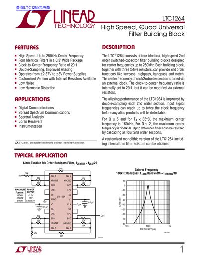
The LTC1264 is a high‑speed, quad universal switched‑capacitor filter building block that offers up to 250 kHz center frequency, low noise, low harmonic distortion, and a fixed 20:1 clock‑to‑center‑frequency ratio. It can be configured for low‑pass, high‑pass, band‑pass, and notch functions, and up to 8th‑order filters can be realized by cascading its four 2nd‑order sections.
The datasheet details absolute maximum ratings, electrical characteristics, pin assignments, and several modes of operation (Modes 1, 1b, 2, 3, 3a, 2n). Typical applications include 8th‑order band‑pass filters with linear phase, and the document includes package dimensions for both PDIP and SOIC variants.
| Operating Supply Range | +2.375 V to +8 V |
|---|---|
| Clock‑to‑Center Frequency Ratio | 20:1 |
| Maximum Clock Frequency | 6 MHz |
| Output Short‑Circuit Current | 3 mA |
| GBW Product | 7 MHz |
| Power Supply Current (typical) | 9 mA to 23 mA |
The device operates from +2.375 V up to +8 V.
The LTC1264 uses a fixed 20:1 clock‑to‑center‑frequency ratio.
The maximum clock frequency is 6 MHz at a 7.5 V supply.
Pin 18 is the clock input pin; it accepts a TTL or CMOS square‑wave clock.