
This guide covers installation, mounting, and status indicator meanings for the Fortinet FortiGate 60E/61E series firewalls.
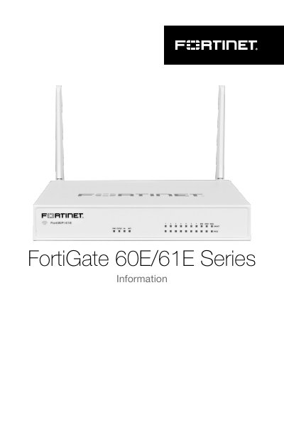
The document provides instructions for installing the FortiGate unit on a flat surface or wall. It details the required clearance, power connection steps using the provided adapter, and antenna attachment procedures for WiFi models.
The guide also explains the status of various LED indicators on different models (FortiGate, FortiGate-POE, and FortiWiFi), covering meanings for Logo, Ethernet ports, Power, HA, Status lights, and specific features like PoE power allocation or WiFi activity.
| Operating Temperature | 0C to 40C |
|---|---|
| Power Input (Standard) | 12V DC, 100-240V AC |
| Power Input (POE Model) | 54V DC, 100-240V AC |
| Ethernet Ports (Standard) | 7 Gigabit Ethernet ports |
| Ethernet Ports (POE Model) | 8 Gigabit Ethernet ports with PoE |
| PoE Max Power | 75W for all ports |
There must be at least 1.5in (3.8cm) of clearance on all sides to allow for adequate airflow.
A flashing green Status LED indicates that the unit is booting up.
No, operation of this device is restricted to indoor use only and antennas having a higher gain are strictly prohibited per regulations.